 EN
EN

Understanding transformer types electrical engineers rely on is essential for anyone involved in power system design, infrastructure planning, or industrial facility management. Transformers are the backbone of modern electrical grids, enabling efficient voltage conversion across transmission, distribution, and end-use stages. Without the right transformer type matched to the right application, power systems would suffer from energy losses, equipment damage, and unreliable supply.
The landscape of transformer types electrical professionals work with spans a wide range of designs, each engineered for specific voltage levels, load conditions, and environmental requirements. From large power transformers stepping down transmission voltages to compact distribution units serving commercial buildings, each category plays a defined role in the power delivery chain. This article breaks down the most common transformer types electrical power systems depend on, explaining their construction, function, and where they fit within the broader grid architecture.
Core Classification of Transformer Types Electrical Power Systems Use
Classification by Voltage Function
The most fundamental way to classify transformer types electrical systems employ is by their voltage conversion function. Step-up transformers increase voltage from a lower level to a higher one, which is critical at power generation stations where electricity must be pushed into high-voltage transmission lines to minimize resistive losses over long distances. Step-down transformers perform the reverse, reducing high transmission voltages to levels suitable for distribution networks or direct end-user consumption.
Isolation transformers represent a third functional category, designed not primarily for voltage change but for electrical isolation between circuits. These are widely used in sensitive industrial and medical environments where galvanic separation between the supply and load is required for safety or signal integrity. Understanding this voltage-function classification is the starting point for selecting the correct transformer types electrical engineers specify for any given project.
Auto-transformers occupy a unique position in this classification. Unlike conventional two-winding designs, they share a single winding between primary and secondary circuits, making them more compact and cost-effective for applications where a modest voltage ratio change is needed. They are commonly found in motor starting circuits and voltage regulation applications across industrial facilities.
Classification by Core Construction
Core construction is another defining characteristic among transformer types electrical designers must evaluate. Core-type transformers wind the coils around a central magnetic core limb, offering straightforward construction and ease of maintenance. Shell-type transformers surround the windings with the magnetic core, providing better mechanical support and improved performance under short-circuit conditions.
The choice between core-type and shell-type construction influences leakage reactance, short-circuit withstand capability, and overall physical footprint. For large power transformers in substations, core-type designs are predominant due to their scalability and established manufacturing base. Shell-type designs are more frequently encountered in specialized high-current, low-voltage applications and certain furnace transformers used in industrial processes.
Power Transformers and Their Role in Transmission Networks
High-Voltage Power Transformers
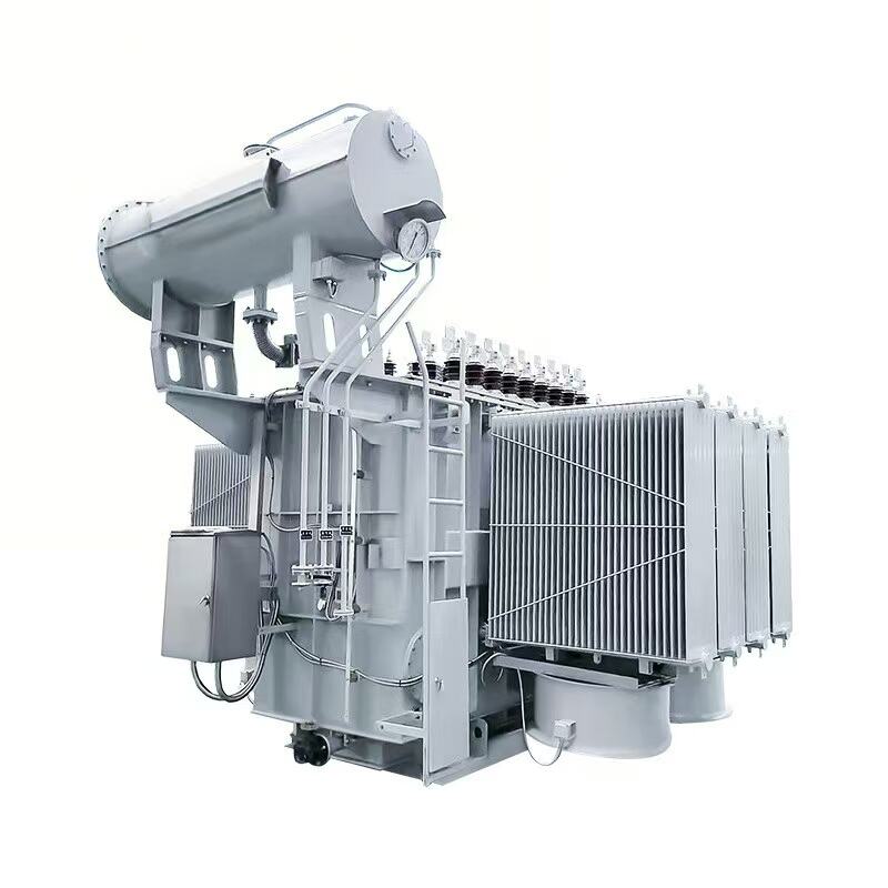
Among all transformer types electrical grids depend on, high-voltage power transformers are the most critical in terms of capacity and consequence. These units operate at transmission voltages ranging from 66 kV up to 765 kV or beyond, handling hundreds of megavolt-amperes of power flow. They are installed at generating stations and major grid substations, forming the primary interface between generation assets and the high-voltage transmission backbone.
Power transformers of this class are engineered for continuous operation under demanding thermal and electrical stress. Their insulation systems, typically oil-paper based, are designed to withstand decades of service with proper maintenance. Cooling systems such as ONAN (oil natural air natural), ONAF (oil natural air forced), and OFAF (oil forced air forced) are selected based on the transformer's rated capacity and the ambient conditions of the installation site.
The reliability of high-voltage power transformers directly determines grid stability. A failure at this level can cascade into widespread outages affecting millions of consumers, which is why condition monitoring, dissolved gas analysis, and periodic testing are standard practice for asset managers responsible for these transformer types electrical utilities operate.
Generator Step-Up Transformers
Generator step-up transformers (GSUs) are a specialized subset of power transformer types electrical generation facilities require. Positioned directly between a generator and the transmission grid, GSUs elevate the generator's output voltage — typically in the range of 11 kV to 25 kV — to the transmission voltage level. Their design must accommodate the specific impedance characteristics of the connected generator and the fault current levels of the grid.
GSUs are subject to unique operational stresses, including frequent load cycling as generation output varies with demand or renewable resource availability. This makes their winding insulation and tap changer mechanisms critical design considerations. For power system planners, selecting the right transformer types electrical generation assets need at the GSU stage directly affects overall plant efficiency and grid interconnection compliance.
Distribution Transformers Serving Commercial and Industrial Loads
Liquid-Filled Distribution Transformers
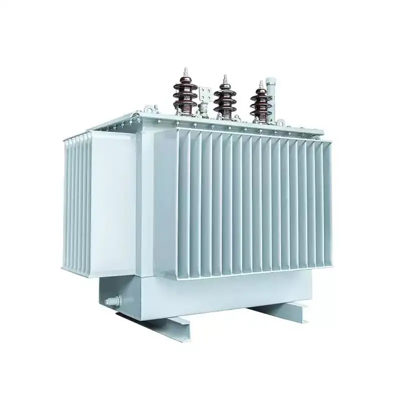
Distribution transformers are among the most widely deployed transformer types electrical infrastructure includes, numbering in the millions across any developed power grid. Liquid-filled distribution transformers use mineral oil or alternative dielectric fluids to provide both insulation and cooling. They are the standard choice for outdoor pad-mounted and pole-mounted installations serving residential neighborhoods, commercial districts, and light industrial facilities.
The S11 series represents a well-established category of oil-immersed distribution transformer types electrical utilities and industrial operators specify for reliable medium-voltage to low-voltage conversion. These units are designed for low no-load losses, which is significant because distribution transformers remain energized continuously regardless of load level. Reducing no-load losses across a large fleet of distribution transformers translates directly into measurable energy savings and lower carbon emissions over the asset's operational life.
Liquid-filled units also benefit from a well-understood maintenance ecosystem. Oil sampling, moisture analysis, and periodic inspection are routine procedures that extend service life well beyond 25 years when properly managed. For operators managing large numbers of transformer types electrical distribution networks rely on, this maintainability is a significant lifecycle cost advantage.
Dry-Type Distribution Transformers
Dry-type transformers use air or resin encapsulation instead of liquid dielectrics, making them the preferred transformer types electrical engineers specify for indoor installations where fire risk or environmental contamination from oil spills is a concern. They are commonly found in commercial buildings, hospitals, data centers, underground substations, and offshore platforms.
Cast resin dry-type transformers offer particularly robust performance in humid or polluted environments. The epoxy resin encapsulation protects windings from moisture ingress and chemical attack, extending service life in challenging conditions. While dry-type units generally carry a higher initial cost than equivalent oil-filled designs, their reduced fire risk and elimination of oil containment infrastructure often justify the premium in sensitive or high-density installations.
Ventilated dry-type transformers represent a more economical variant within this category, relying on natural or forced air circulation for cooling. These are suitable for clean, controlled indoor environments and are widely used in commercial HVAC systems, industrial motor control centers, and renewable energy inverter stations where transformer types electrical designers select must meet strict space and safety constraints.
Specialty Transformer Types Electrical Engineers Specify for Unique Applications
Instrument Transformers
Instrument transformers are a distinct family of transformer types electrical protection and metering systems depend on. Current transformers (CTs) and voltage transformers (VTs or PTs) scale down high-magnitude currents and voltages to standardized low-level signals that protection relays, energy meters, and monitoring equipment can safely process. Without accurate instrument transformers, the measurement and protection of high-voltage power systems would be impractical.
The accuracy class of an instrument transformer is a critical specification. Metering-class CTs and VTs must maintain tight ratio and phase angle errors across a defined burden range to ensure billing accuracy. Protection-class units prioritize performance under fault conditions, maintaining accuracy even when primary currents reach many times the rated value during short circuits. Selecting the correct accuracy class is one of the most consequential decisions when specifying these transformer types electrical protection engineers work with.
Furnace and Rectifier Transformers
Industrial processes such as electric arc furnace steelmaking, electrochemical refining, and large-scale rectifier installations require transformer types electrical equipment manufacturers design specifically for high-current, low-voltage output with exceptional short-circuit withstand capability. Furnace transformers must tolerate the violent and unpredictable load fluctuations generated by arc furnace operation, including frequent short circuits and rapid load swings that would damage conventional distribution transformers.
Rectifier transformers supply AC power to large rectifier bridges used in aluminum smelting, chlorine production, and DC traction systems. Their design incorporates multiple secondary windings with specific phase displacement to reduce harmonic distortion in the supply network. These are among the most technically demanding transformer types electrical industrial engineers encounter, requiring close collaboration between the transformer manufacturer and the process equipment supplier to achieve optimal system performance.
Traction Transformers
Railway electrification systems rely on traction transformers, a specialized category of transformer types electrical infrastructure planners must account for in transit and freight rail projects. These units convert grid supply voltages to the specific traction voltages used by railway systems, such as 25 kV single-phase AC or 1.5 kV and 3 kV DC systems. Traction transformers must handle highly variable and asymmetric loading as trains accelerate and brake across the network.
The single-phase loading characteristic of many traction systems creates voltage unbalance in the three-phase supply grid, which traction transformer designs must mitigate through special winding configurations such as Scott-T or Le Blanc arrangements. This makes traction transformers one of the more technically nuanced transformer types electrical power system engineers must understand when designing railway power supply infrastructure.
Key Selection Criteria Across All Transformer Types Electrical Projects Require
Voltage Ratio, Impedance, and Tap Range
Regardless of which transformer types electrical engineers are evaluating, voltage ratio accuracy, leakage impedance, and tap changer range are universal selection parameters. The voltage ratio must match the system's nominal voltage levels at both primary and secondary terminals. Leakage impedance determines fault current contribution and voltage regulation under load — a higher impedance limits fault current but increases voltage drop under heavy loading.
Tap changers, either off-circuit or on-load (OLTC), allow voltage ratio adjustment to compensate for supply voltage variations and load-driven voltage drops. On-load tap changers are essential for transformer types electrical transmission and primary distribution systems use, where voltage must be regulated continuously without interrupting supply. Off-circuit tap changers are adequate for distribution transformers where occasional voltage adjustment during planned outages is acceptable.
Efficiency Standards and Loss Evaluation
Modern procurement of transformer types electrical utilities and large industrial operators specify is increasingly governed by efficiency standards. Regulations in major markets mandate minimum efficiency levels, expressed through maximum allowable no-load and load losses. Compliance with standards such as IEC 60076, ANSI/IEEE C57, or regional equivalents is a baseline requirement for most public utility and large commercial procurements.
Total owning cost (TOC) methodology evaluates transformer types electrical buyers are comparing by capitalizing both no-load and load losses over the expected service life. A transformer with lower losses may carry a higher purchase price but deliver superior lifecycle economics. This approach is standard practice among sophisticated utility and industrial buyers who recognize that the purchase price represents only a fraction of the total cost of transformer ownership over a 30-year service life.
FAQ
What is the difference between a power transformer and a distribution transformer?
Power transformers are among the transformer types electrical transmission systems use, operating at high voltages and large capacities to move bulk power across the grid. Distribution transformers operate at lower voltages and smaller capacities, serving as the final voltage conversion stage before power reaches end consumers. The two categories differ in design priorities, with power transformers optimized for efficiency at full load and distribution transformers optimized for low no-load losses due to continuous energization.
Why are there so many different transformer types electrical engineers must choose from?
The diversity of transformer types electrical professionals encounter reflects the wide range of voltage levels, load characteristics, environmental conditions, and safety requirements across different power system applications. A transformer serving a high-voltage transmission substation faces entirely different electrical, thermal, and mechanical demands than one supplying a hospital building or an arc furnace. Each application requires a design optimized for its specific operating conditions, which is why the range of transformer types electrical catalogs present is so broad.
How do I determine which transformer types electrical specifications are most important for my project?
The most critical specifications depend on the application. For transmission and primary substation transformer types electrical planners are selecting, voltage ratio, impedance, cooling class, and tap changer type are primary considerations. For distribution transformer types electrical facility engineers are specifying, no-load losses, short-circuit impedance, and installation environment (indoor versus outdoor, fire risk level) typically drive the selection. Engaging with a qualified transformer engineer early in the project design phase ensures that all relevant parameters are identified and correctly specified.
Are oil-filled transformer types electrical systems use being replaced by dry-type units?
Oil-filled transformer types electrical grids rely on remain dominant for outdoor and high-capacity applications due to their superior thermal performance, lower cost at large ratings, and well-established maintenance infrastructure. Dry-type units have expanded their market share in indoor, urban, and environmentally sensitive installations where oil containment is impractical or fire risk is a primary concern. The two technologies are complementary rather than competitive, with each category holding clear advantages in its appropriate application domain.
Table of Contents
- Core Classification of Transformer Types Electrical Power Systems Use
- Power Transformers and Their Role in Transmission Networks
- Distribution Transformers Serving Commercial and Industrial Loads
- Specialty Transformer Types Electrical Engineers Specify for Unique Applications
- Key Selection Criteria Across All Transformer Types Electrical Projects Require
-
FAQ
- What is the difference between a power transformer and a distribution transformer?
- Why are there so many different transformer types electrical engineers must choose from?
- How do I determine which transformer types electrical specifications are most important for my project?
- Are oil-filled transformer types electrical systems use being replaced by dry-type units?
