

Power transformers are critical components in electrical distribution systems that require sophisticated protection mechanisms to operate safely and reliably. When transformers experience internal faults, electrical arcs, or thermal events, they can generate significant internal pressure that threatens the integrity of the transformer tank. A pressure relief valve serves as an essential safety device designed to protect transformers from catastrophic failure by automatically releasing excessive internal pressure. Understanding how these valves respond to sudden overpressure events is crucial for power system engineers, maintenance personnel, and facility operators who rely on transformer protection systems to maintain electrical grid stability.
Fundamental Principles of Transformer Pressure Relief Systems
Operating Mechanism of Pressure Relief Valves
The pressure relief valve operates on a spring-loaded mechanism that remains closed under normal operating conditions while continuously monitoring internal transformer pressure. When internal pressure exceeds the predetermined setpoint, typically between 7 to 10 psi above atmospheric pressure, the valve automatically opens to release gases and reduce internal pressure. This spring-loaded design ensures that the valve responds proportionally to pressure increases, opening wider as pressure continues to rise and closing automatically when pressure returns to safe levels.
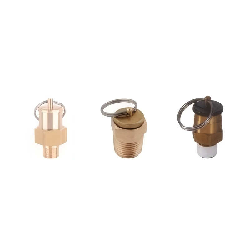
The valve assembly consists of several key components including a spring-loaded disc, valve seat, guide assembly, and weatherproof housing. The spring tension is factory-calibrated to ensure precise opening pressure, while the disc design provides a tight seal during normal operation. Modern pressure relief valve designs incorporate materials resistant to transformer oil vapors and environmental conditions, ensuring long-term reliability in outdoor installations.
Pressure Threshold and Response Characteristics
Transformer pressure relief valves are engineered with specific pressure thresholds that balance protection requirements with operational stability. The typical opening pressure ranges from 7 to 10 psi gauge pressure, though this can vary based on transformer size, voltage class, and manufacturer specifications. This relatively low pressure threshold ensures rapid response to internal faults while preventing nuisance trips during normal load variations or ambient temperature changes.
The response time of a pressure relief valve is typically measured in milliseconds, making it one of the fastest-acting protective devices in transformer systems. This rapid response capability is essential because internal transformer faults can generate pressure increases at extremely high rates, potentially reaching dangerous levels within seconds if not properly managed.
Types of Overpressure Events in Transformers
Internal Arc Faults and Gas Generation
Internal arc faults represent one of the most severe overpressure scenarios that a pressure relief valve must address. When electrical insulation fails within the transformer, high-energy arcing occurs between conductors or between conductors and grounded components. These arcs generate intense heat that rapidly decomposes transformer oil and solid insulation materials, producing large volumes of gases including hydrogen, methane, acetylene, and carbon monoxide.
The rate of gas generation during arc faults can be extraordinarily high, with internal pressure rising from normal levels to critical thresholds in less than one second. The pressure relief valve must respond instantly to prevent tank rupture, which could result in oil spillage, fire hazards, and catastrophic equipment damage. The valve design accounts for these extreme pressure rise rates by incorporating large flow capacity and minimal opening force requirements.
Thermal Events and Oil Expansion
Thermal events in transformers can also trigger pressure relief valve operation, though typically at slower pressure rise rates than arc faults. Overloading, cooling system failures, or blocked oil circulation can cause transformer oil temperatures to rise significantly, resulting in thermal expansion and increased internal pressure. Additionally, severe overheating can cause oil degradation and gas evolution, further contributing to pressure increases.
During thermal events, the pressure relief valve provides protection against gradual pressure buildup while allowing the transformer protection systems time to detect and respond to the underlying thermal condition. The valve prevents pressure from reaching levels that could damage the transformer tank or compromise other protective devices while maintaining system integrity during emergency conditions.
Response Mechanisms and Operating Sequence
Initial Pressure Detection and Valve Opening
When sudden overpressure occurs within a transformer, the pressure relief valve initiates its response sequence through direct pressure sensing on the spring-loaded disc assembly. The internal pressure acts against the valve disc, creating an upward force that competes with the downward spring force. As pressure continues to increase beyond the setpoint threshold, the upward pressure force overcomes the spring force, causing the disc to lift from its seat and create an opening for gas release.
The initial opening of the pressure relief valve creates a relatively small flow area, but as pressure continues to increase, the disc lifts higher, progressively increasing the flow capacity. This proportional response characteristic ensures that the valve can handle both gradual pressure increases and sudden pressure spikes effectively. The valve opening area increases rapidly with pressure, providing maximum flow capacity when it is needed most during severe fault conditions.
Gas Flow and Pressure Equalization
Once the pressure relief valve opens, gases and oil vapors flow through the valve opening to the atmosphere, rapidly reducing internal transformer pressure. The flow rate through the valve depends on the pressure differential, valve opening area, and the physical properties of the gases being released. During arc fault conditions, the valve may release a mixture of decomposition gases and vaporized oil, while thermal events typically result in the release of heated air and oil vapors.
The pressure equalization process continues until internal transformer pressure drops below the valve closing threshold, which is typically 1 to 2 psi lower than the opening pressure. This pressure differential, known as blowdown, prevents valve chattering and ensures stable operation during pressure fluctuations. The valve disc gradually returns to its seated position as the spring force overcomes the reduced internal pressure.
Integration with Transformer Protection Systems
Coordination with Gas Detection Systems
Modern transformer installations integrate pressure relief valves with sophisticated gas detection and monitoring systems to provide comprehensive protection coverage. Dissolved gas analysis systems continuously monitor transformer oil for fault gases, providing early warning of developing problems before pressure relief valve operation becomes necessary. When both systems detect abnormal conditions simultaneously, operators can quickly identify the severity and nature of the transformer fault.
The pressure relief valve serves as a backup protection system that operates independently of electronic monitoring systems, ensuring protection even during power outages or communication failures. This redundancy is essential for critical transformer installations where loss of the transformer could result in widespread power outages or significant economic impacts.
Alarm and Monitoring Integration
Many pressure relief valve installations include position monitoring switches that detect valve operation and transmit alarm signals to control systems. These monitoring systems provide immediate notification when the pressure relief valve operates, enabling rapid response from maintenance personnel and system operators. The alarm integration allows operators to distinguish between normal pressure variations and actual fault conditions requiring immediate attention.
Advanced monitoring systems can also track valve operation history, providing valuable data for transformer condition assessment and maintenance planning. This information helps identify patterns in transformer operation that may indicate developing problems or the need for preventive maintenance actions.
Design Considerations and Selection Criteria
Flow Capacity and Sizing Requirements
Proper sizing of a pressure relief valve requires careful consideration of the maximum expected gas generation rate during fault conditions and the allowable internal pressure limits of the transformer tank. The valve must provide sufficient flow capacity to prevent internal pressure from exceeding the mechanical strength limits of the transformer tank while accounting for the dynamic nature of fault-generated gas production.
Industry standards provide guidelines for calculating minimum flow capacity requirements based on transformer size, oil volume, and fault energy levels. These calculations consider the worst-case scenario of a high-energy internal arc fault that generates the maximum possible gas volume in the shortest time. The selected pressure relief valve must exceed these minimum capacity requirements while maintaining reliable sealing during normal operation.
Environmental and Application Factors
The selection and installation of pressure relief valves must account for environmental conditions including temperature extremes, humidity, contamination, and seismic requirements. Valves installed in outdoor substations must withstand wide temperature ranges, ice loading, and ultraviolet radiation while maintaining consistent operating characteristics. Special materials and coatings may be required for installations in corrosive environments or areas with high contamination levels.
Application-specific factors such as transformer voltage class, installation location, and maintenance accessibility also influence valve selection. High-voltage transformer installations may require additional electrical isolation considerations, while underground or restricted-access installations may need remote monitoring capabilities or extended maintenance intervals.
Maintenance and Testing Procedures
Periodic Inspection and Functional Testing
Regular maintenance of pressure relief valves is essential to ensure reliable operation when needed. Periodic inspections should verify proper valve mounting, check for external damage or corrosion, and confirm that the valve discharge path remains unobstructed. Visual inspection of the valve seat area can reveal signs of leakage or contamination that might affect sealing performance.
Functional testing of pressure relief valves typically involves applying controlled pressure to verify opening and closing pressure settings. This testing should be performed using appropriate pressure sources and measuring equipment to ensure accuracy. Testing procedures must also verify that the valve reseats properly after operation and maintains its seal integrity during normal operating pressures.
Valve Replacement and Upgrade Considerations
Pressure relief valves have finite service lives and may require replacement due to wear, contamination, or changes in protection requirements. Replacement planning should consider valve age, operating history, and compatibility with existing transformer systems. Upgraded valve designs may offer improved performance, enhanced monitoring capabilities, or better environmental resistance.
When replacing pressure relief valves, careful attention must be paid to pressure settings, flow capacity, and mounting compatibility. The replacement valve must meet or exceed the performance specifications of the original valve while maintaining proper integration with transformer protection and monitoring systems.
Advanced Technologies and Future Developments
Smart Valve Technology and Remote Monitoring
Emerging technologies are introducing intelligent pressure relief valve designs that incorporate advanced sensing and communication capabilities. These smart valves can provide real-time pressure monitoring, valve position feedback, and predictive maintenance alerts through integrated sensors and wireless communication systems. This technology enables continuous monitoring of valve condition and performance without requiring manual inspection or testing.
Remote monitoring capabilities allow operators to track pressure relief valve status from centralized control centers, improving response times during emergency conditions and enabling proactive maintenance planning. Integration with digital substation systems provides seamless data exchange and automated response coordination with other protection systems.
Enhanced Materials and Design Innovations
Ongoing research and development efforts focus on improving pressure relief valve materials and design features to enhance performance and reliability. Advanced materials with superior corrosion resistance, temperature stability, and mechanical properties are being incorporated into valve components to extend service life and reduce maintenance requirements.
Design innovations include improved flow characteristics, reduced opening pressures, and enhanced sealing technologies that provide better performance across a wider range of operating conditions. These developments aim to improve overall transformer protection while reducing the total cost of ownership for electrical utility and industrial customers.
FAQ
What causes a pressure relief valve to operate in a transformer
A pressure relief valve operates when internal transformer pressure exceeds its predetermined setpoint, typically 7 to 10 psi above atmospheric pressure. Common causes include internal arc faults that rapidly decompose oil and insulation materials, thermal events causing oil expansion, gas accumulation from electrical faults, or mechanical damage to internal components. The valve automatically opens to release excess pressure and protect the transformer tank from rupture or damage.
How quickly does a pressure relief valve respond to overpressure
Pressure relief valves respond to overpressure within milliseconds of reaching their opening threshold. This extremely fast response time is critical because internal transformer faults can generate pressure increases at very high rates, potentially reaching dangerous levels within seconds. The spring-loaded mechanism provides immediate pressure sensing and valve opening without requiring external power or control signals, ensuring reliable protection even during system emergencies.
Can a pressure relief valve reset automatically after operation
Yes, pressure relief valves are designed to reset automatically when internal pressure drops below the closing threshold, typically 1 to 2 psi lower than the opening pressure. This automatic reset capability allows the valve to provide continuous protection without manual intervention. However, after any pressure relief valve operation, the transformer should be thoroughly inspected to identify and address the underlying cause of the overpressure condition before returning to service.
What maintenance is required for transformer pressure relief valves
Pressure relief valves require periodic visual inspection for external damage, corrosion, or obstruction of the discharge path. Functional testing should verify proper opening and closing pressure settings using calibrated pressure sources. Internal inspection may be necessary to check valve seat condition and sealing integrity. Maintenance intervals typically range from annual inspections to complete overhaul every 5 to 10 years, depending on operating conditions and manufacturer recommendations.
Table of Contents
- Fundamental Principles of Transformer Pressure Relief Systems
- Types of Overpressure Events in Transformers
- Response Mechanisms and Operating Sequence
- Integration with Transformer Protection Systems
- Design Considerations and Selection Criteria
- Maintenance and Testing Procedures
- Advanced Technologies and Future Developments
- FAQ
