 EN
EN

Understanding transformer types electrical engineers work with every day is fundamental to designing reliable power systems, selecting the right equipment, and ensuring safe energy distribution across industrial and commercial applications. Whether you are specifying equipment for a new substation, upgrading an aging grid infrastructure, or evaluating options for a manufacturing facility, knowing how transformers are defined and differentiated gives you a decisive advantage in both procurement and engineering decisions.
The classification of transformer types electrical professionals rely on is not arbitrary. It reflects real differences in construction, operating principles, insulation methods, voltage levels, and intended applications. A clear grasp of these categories helps engineers, procurement specialists, and facility managers make informed choices rather than defaulting to generic specifications. This article breaks down the major classification frameworks and explains what each category means in practical terms.
The Core Definition of a Transformer and Why Classification Matters
What a Transformer Actually Does
A transformer is an electromagnetic device that transfers electrical energy between two or more circuits through the principle of electromagnetic induction. It does this without any direct electrical connection between the input and output circuits, relying instead on a shared magnetic core and carefully wound coils. The ratio of turns between the primary and secondary windings determines whether the output voltage is stepped up or stepped down relative to the input.
This seemingly simple mechanism underpins virtually every segment of modern electrical infrastructure, from high-voltage transmission lines carrying power across hundreds of kilometers to small distribution units serving individual buildings. The diversity of applications is precisely why transformer types electrical engineers encounter span such a wide range of designs, sizes, and specifications.
Without a structured classification system, comparing or specifying transformers would be chaotic. Classification gives engineers a shared language and a logical framework for matching equipment to requirements. It also helps regulatory bodies set standards, manufacturers design product lines, and end users evaluate technical datasheets with confidence.
Why Classification Is an Engineering Tool, Not Just a Label
Classifying transformer types electrical teams work with is not merely an academic exercise. Each classification axis — whether based on voltage level, cooling method, core construction, or application — carries direct implications for installation requirements, maintenance schedules, safety protocols, and total cost of ownership. Misclassifying or ignoring these distinctions can lead to equipment underperformance, premature failure, or serious safety hazards.
For example, selecting a dry-type transformer for an outdoor substation application where an oil-immersed unit is required can result in inadequate thermal management and shortened service life. Similarly, applying a distribution transformer in a role that demands a power transformer will result in voltage regulation problems and potential overload conditions. Classification is therefore a practical decision-making tool embedded in every serious engineering workflow.
Classification by Voltage Level and Power Rating
Power Transformers for Transmission Networks
Among the most significant transformer types electrical grids depend on are power transformers, which operate at high and extra-high voltage levels, typically above 33 kV. These units are installed at generating stations and large transmission substations where bulk electrical energy must be stepped up for long-distance transmission or stepped down before entering regional distribution networks. Their ratings commonly range from several MVA to hundreds of MVA.
Power transformers are engineered for continuous full-load operation and are designed with efficiency as a primary concern, since even small percentage losses translate into significant energy waste at the scale they operate. Their core and winding materials, insulation systems, and cooling arrangements are all optimized for sustained high-power performance over decades of service life.
Because of their critical role in grid stability, power transformers are subject to rigorous testing standards and are typically equipped with sophisticated monitoring systems that track temperature, oil quality, load current, and other parameters in real time. Any failure at this level can cascade into widespread outages, making reliability engineering a central concern in their design and specification.
Distribution Transformers for End-Use Delivery
Distribution transformers represent another major category within transformer types electrical utilities deploy at the final stage of the power delivery chain. These units step down medium-voltage distribution levels — typically between 11 kV and 33 kV — to the low voltages used directly by residential, commercial, and light industrial consumers, such as 400 V or 230 V.
Unlike power transformers, distribution transformers are designed to handle variable and often unpredictable load profiles. They must perform efficiently across a wide range of loading conditions, from near-zero demand during off-peak hours to full rated capacity during peak consumption periods. This operational flexibility is built into their design through careful core material selection and winding geometry.
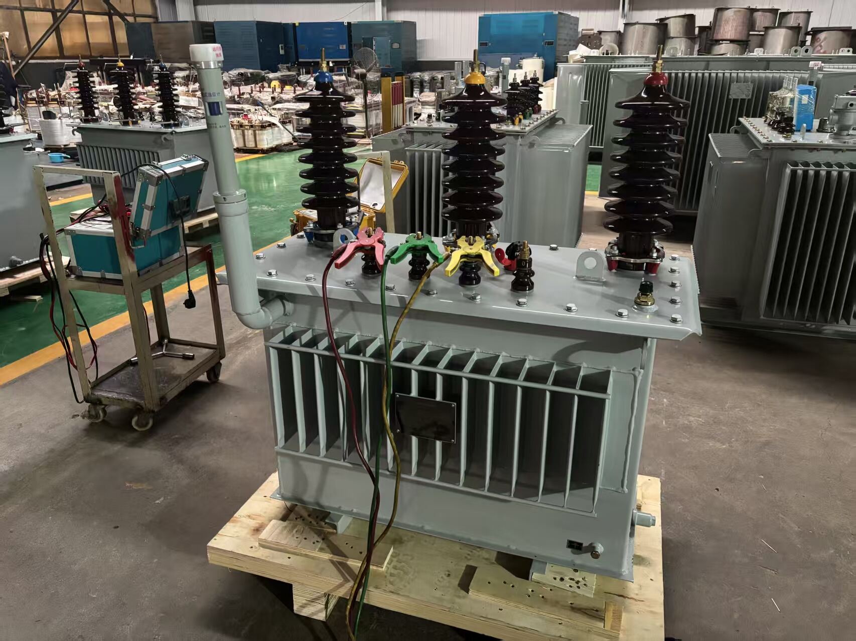
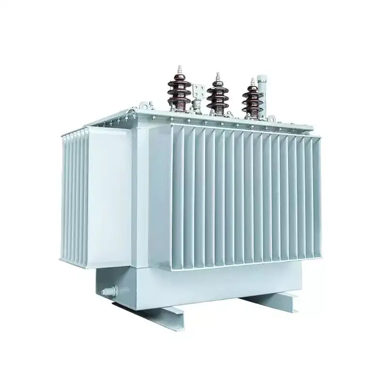
The S11 series of oil-immersed distribution transformers is a well-established product family in this category, known for its low no-load losses and compliance with modern energy efficiency standards. Distribution transformers in this class are widely deployed in urban and rural grid infrastructure, industrial parks, and commercial developments where reliable, efficient voltage conversion at the point of delivery is essential.
Classification by Insulation and Cooling Method
Oil-Immersed Transformers
Oil-immersed units are among the most widely used transformer types electrical infrastructure projects specify for medium and high-voltage applications. In these designs, the core and windings are submerged in transformer oil, which serves a dual purpose: it provides electrical insulation between live components and the tank, and it acts as a cooling medium by circulating heat away from the windings to the tank surface or external radiators.
Mineral oil has been the traditional insulating fluid of choice due to its excellent dielectric properties, thermal stability, and relatively low cost. More recently, synthetic esters and natural ester fluids have gained traction in applications where fire safety or environmental sensitivity is a concern, since these fluids offer higher flash points and improved biodegradability compared to conventional mineral oil.
Oil-immersed transformer types electrical engineers specify for outdoor substations and high-load industrial applications benefit from well-established maintenance practices, including periodic oil sampling and dissolved gas analysis, which can detect developing faults long before they become critical failures. This predictive maintenance capability is a significant operational advantage in high-value installations.
Dry-Type Transformers
Dry-type transformers use air as the primary cooling and insulation medium, eliminating the need for liquid insulating fluids entirely. The windings are typically encapsulated in resin or cast in epoxy, providing robust mechanical protection and resistance to moisture, dust, and chemical contaminants. This makes dry-type units particularly well suited for indoor installations in environments where oil leakage would pose unacceptable fire or contamination risks.
Common applications for dry-type transformer types electrical specifiers choose include commercial buildings, hospitals, data centers, underground transit systems, and offshore platforms. In these settings, the absence of flammable liquid insulation is a critical safety advantage, and the reduced maintenance requirements compared to oil-immersed units translate into lower lifecycle costs despite the typically higher initial purchase price.
Dry-type units are generally available in ratings up to around 30 MVA and voltages up to approximately 36 kV, though the majority of installations fall within the distribution voltage range. Their thermal performance is managed through natural air convection in smaller units and forced-air cooling systems in larger ratings, with cooling class designations standardized under IEC and other international frameworks.
Classification by Core Construction and Phase Configuration
Core-Type and Shell-Type Constructions
The physical arrangement of the magnetic core relative to the windings defines two fundamental construction approaches among transformer types electrical manufacturers produce. In core-type construction, the windings surround the magnetic core limbs, with the core forming a simple rectangular or cruciform cross-section path for magnetic flux. This design is straightforward to manufacture, easy to inspect, and well suited to high-voltage applications where winding insulation must be carefully managed.
Shell-type construction reverses this relationship: the core surrounds and encloses the windings, providing a more compact magnetic circuit with lower leakage flux. Shell-type designs are often preferred for low-voltage, high-current applications and for units where mechanical robustness under short-circuit forces is a priority. The choice between these two construction approaches involves trade-offs in manufacturing complexity, material utilization, and performance characteristics under fault conditions.
Both core-type and shell-type transformer types electrical engineers specify are available in single-phase and three-phase configurations, with the three-phase design being dominant in power and distribution applications due to its superior efficiency and lower material cost per unit of power transferred compared to using three separate single-phase units.
Single-Phase and Three-Phase Configurations
Single-phase transformer types electrical systems use in residential distribution and specialized industrial applications transfer power through a single alternating current circuit. They are simpler in construction, easier to transport in large ratings, and can be connected in banks to form three-phase systems when required. In some transmission applications, using three single-phase units instead of one three-phase unit offers logistical advantages, since individual units are easier to transport to remote sites and a spare single-phase unit can serve as backup for any of the three phases.
Three-phase transformers integrate all three phases within a single core and tank assembly, making them more compact, more efficient, and less expensive per kVA than equivalent single-phase banks. The vast majority of transformer types electrical utilities and industrial facilities install for distribution and power applications are three-phase units, reflecting the dominance of three-phase AC systems in modern electrical infrastructure worldwide.
The winding connection configuration — whether delta or star on the primary and secondary sides — adds another layer of classification that affects voltage ratios, fault current behavior, harmonic management, and grounding arrangements. Common configurations such as Dyn11, YNd11, and YNyn0 are standardized designations that communicate both the winding topology and the phase displacement between primary and secondary voltages, information that is critical for parallel operation and system protection design.
Classification by Application and Special Function
Instrument Transformers for Measurement and Protection
Not all transformer types electrical systems incorporate are designed for power transfer. Instrument transformers — comprising current transformers and voltage transformers — are designed specifically to produce scaled-down replicas of system currents and voltages for use by metering equipment and protective relays. They isolate sensitive measurement and control circuits from the high voltages and currents present in the primary power system while providing accurate proportional signals.
Current transformers are connected in series with the primary circuit and produce a secondary current proportional to the primary current, typically scaled to standard values such as 1 A or 5 A for relay and meter inputs. Voltage transformers are connected in parallel with the circuit being measured and step down system voltage to standard levels such as 110 V or 100 V. The accuracy class of these units is a critical specification, since errors in measurement directly affect the accuracy of energy billing and the reliability of protection system operation.
Instrument transformer types electrical protection engineers specify must meet stringent accuracy and burden requirements defined by standards such as IEC 61869. Their performance under fault conditions — particularly the ability of current transformers to accurately reproduce high fault currents without saturation — is a key factor in ensuring that protection relays operate correctly and selectively during system disturbances.
Autotransformers and Special-Purpose Designs
Autotransformers represent a distinct category among transformer types electrical engineers encounter in transmission and industrial applications. Unlike conventional two-winding transformers, autotransformers share a common winding between the primary and secondary circuits, with the secondary being a tapped portion of the primary winding. This design results in a more compact and efficient unit for applications where the voltage ratio is relatively close to unity, such as interconnecting transmission systems operating at different but similar voltage levels.
The trade-off with autotransformers is the direct electrical connection between primary and secondary circuits, which means that faults on one side can more readily propagate to the other. This characteristic requires careful consideration in system protection design and limits their use in applications where galvanic isolation between circuits is required for safety or operational reasons.
Other special-purpose transformer types electrical projects may require include furnace transformers for electric arc furnace applications, rectifier transformers for industrial DC power supplies, traction transformers for railway electrification systems, and phase-shifting transformers for controlling power flow in meshed transmission networks. Each of these designs incorporates specific features tailored to the demanding and often unusual electrical and mechanical conditions of their target applications.
FAQ
What is the difference between a power transformer and a distribution transformer?
A power transformer operates at high voltage levels, typically above 33 kV, and is used at generating stations and major transmission substations to transfer bulk electrical energy over long distances. A distribution transformer operates at medium to low voltage levels and delivers power directly to end consumers. The two types differ in their voltage ratings, power ratings, loading profiles, and design priorities, with power transformers optimized for continuous full-load efficiency and distribution transformers designed for variable load performance.
Why are there so many different transformer types electrical engineers must choose from?
The diversity of transformer types electrical systems require reflects the enormous range of operating conditions, voltage levels, environmental constraints, and application requirements found across modern electrical infrastructure. A transformer serving a high-voltage transmission substation faces completely different thermal, electrical, and mechanical demands than one installed inside a commercial building or used for precision measurement in a protection system. Each classification category exists because a single universal design cannot efficiently and safely serve all these different roles.
How does the cooling method affect transformer selection?
The cooling method directly affects a transformer's thermal performance, installation environment suitability, maintenance requirements, and fire safety profile. Oil-immersed transformer types electrical engineers specify for outdoor and high-power applications offer excellent thermal management and well-established maintenance practices but require containment measures for the insulating fluid. Dry-type units are preferred for indoor and fire-sensitive environments due to the absence of flammable liquid, though they typically have higher initial costs and are limited to lower voltage and power ratings compared to oil-immersed designs.
What does the winding connection designation such as Dyn11 mean for a distribution transformer?
The winding connection designation communicates the topology of both the primary and secondary windings and the phase displacement between them. In Dyn11, 'D' indicates a delta-connected primary winding, 'y' indicates a star-connected secondary winding, 'n' indicates that the star point of the secondary is brought out as a neutral terminal, and '11' indicates a 30-degree phase displacement between primary and secondary voltages, equivalent to the 11 o'clock position on a clock face. This information is essential for ensuring correct parallel operation between transformer types electrical utilities connect to the same busbar and for designing appropriate system protection schemes.
Table of Contents
- The Core Definition of a Transformer and Why Classification Matters
- Classification by Voltage Level and Power Rating
- Classification by Insulation and Cooling Method
- Classification by Core Construction and Phase Configuration
- Classification by Application and Special Function
-
FAQ
- What is the difference between a power transformer and a distribution transformer?
- Why are there so many different transformer types electrical engineers must choose from?
- How does the cooling method affect transformer selection?
- What does the winding connection designation such as Dyn11 mean for a distribution transformer?
